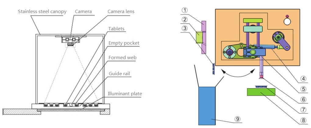
Schematic Diagram: Vision Inspection Tracking and Automated Rejection Mechanism
11/01/2026
Engineering Note: This technical documentation was originally published in 2019. It has been comprehensively updated on November 1, 2026, to reflect the latest advancements in PLC shift register tracking, optical illumination strategies, and automated rejection architectures.
In the pharmaceutical industry, the quality assurance of solid dosage forms relies heavily on automated Machine Vision. Modern Blister Packaging Machines employ high-speed camera systems to verify product presence, color, geometric integrity, and to detect cross-contamination. Inspection parameters are highly customizable based on the packaging material: while opaque Alu-Alu formats require top-mounted coaxial lighting, transparent PVC/PVDC webs utilize high-contrast backlight illumination.
1. Optical Detection Principle (Backlight Illumination)
For basic PVC film applications, the camera is securely housed within a stainless steel canopy, oriented downward toward the formed web. An illuminant plate is installed directly beneath the web track.
- Qualified Cavity: When a tablet is correctly fed, it physically blocks the light emitting from the lower plate, creating a solid dark pixel cluster in the imaging software.
- Faulty Cavity (Missing Product): If a pocket is empty, the backlight freely penetrates the transparent PVC. The camera captures this high-intensity light transmission, immediately identifying and flagging the cavity as defective.
2. PLC Shift Register Tracking (Stroke Calculation)
Once a defect is logged, the system must track this specific faulty pocket as it travels downstream through the sealing, embossing, and punching stations. This tracking is managed by a PLC shift register, which counts the “number of strokes” (kinematic indexing cycles). Because the physical web distance between the camera axis and the punching die is fixed, the operator must strictly calibrate this stroke count via the HMI. Incorrect parameter inputs will result in a synchronization failure, causing the mechanism to reject qualified blister cards while allowing defective ones to pass.
3. End-of-Line Automated Rejection Mechanism
Upon reaching the punching station, the web is sheared by the convex and concave dies. Guided by the PLC shift register, the automated pick-up mechanism [4] executes a split-path sequence:
- Qualified Products: The suction cups [6] securely grip the defect-free blister cards [7] and transfer them seamlessly onto the downstream conveyor belt [8] for subsequent cartoning.
- Defective Products: If the stroke data indicates a flagged card, the vacuum suction is bypassed or redirected, allowing the faulty blister card [3] to drop strictly into the designated waste container [9] via gravity chute.