Schematic Diagram: DPH Series Blister Machine Servo Traction Length Calculation and Pitch Calibration SOP
02/05/2019
Compared to the DPP series platen-sealing architecture, the DPH series Blister Packaging Machine features a significantly larger forming area and a higher downstream cutting frequency. Consequently, the servo-driven traction length between the forming and cutting stations must be precisely calculated based on their kinematic speed ratio (multiplier). For instance, smaller blister dimensions necessitate a larger speed ratio (e.g., 1:2, 1:3, or 1:4), meaning for every single stroke of the forming station, the cutting station executes 2, 3, or 4 punching cycles.
1. Traction Length Calculation (Example: 57 x 80mm Blister)
For a standard 57 x 80mm format, the kinematic ratio is typically 1:4 (Forming Output: 12 cards/cycle; Cutting Output: 3 cards/cycle). The required forming traction length is calculated as follows:
- Formula: (Blister Width + Skeleton Waste Trim) × Multiplier. Assuming a standard 1mm waste skeleton between cards, the HMI input value must be: (57mm + 1mm) × 4 = 232mm.

2. Pitch Calibration and HMI Adjustment
A single forming cycle produces 4 continuous rows of blister cavities. Proper alignment dictates strict dimensional tolerances:
- Parameter A (Intra-cycle Pitch): The fixed physical distance between rows 1, 2, 3, and 4, which is permanently machined into the forming mold tooling.
- Parameter B (Inter-cycle Pitch): The adjustable indexing distance between the last row of the current cycle (row 4) and the first row of the subsequent cycle (row 5).
- Calibration: Measure A and B using a digital caliper. If B < A, the traction length is insufficient (increase value via HMI). If B > A, the traction length is excessive (decrease value via HMI). The critical constraint is B = A to ensure synchronous entry into the rotary sealing mold.
3. Mechanical Validation via Tooling Geometry
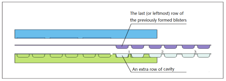
To physically validate the traction accuracy, the DPH lower forming mold is engineered with an extra “validation row” of cavities at its extreme downstream edge (rightmost). During intermittent indexing, if the final row of the previously formed blister web perfectly nests into this validation row when the molds close, the traction length is geometrically accurate. Any misalignment indicates an incorrect indexing length requiring HMI recalibration.