Standard Operating Procedure: Cold-Forming Mould Installation & Calibration (DPP Series)
04/21/2017
Proper installation and calibration of the cold-forming (Alu/Alu) mould on the DPP series Blister Packaging Machine is critical to ensure barrier integrity and prevent material fatigue. This guide outlines the mechanical working principles, step-by-step installation, and precision adjustment procedures.
1. Mechanical Working Principle
The cold-forming station operates through precise mechanical synchronization:
-
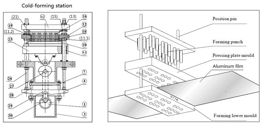
- Clamping Phase: The forming cam drives the lower mould (18) upward, clamping the aluminum laminate film tightly against the press plate (12).
-
- Drawing Phase: Simultaneously, the eccentric wheel (1) drives the cover plate (14.2) downward. The punch dies (16) installed on the cover plate physically elongate the clamped aluminum film into the lower mould to form the blister cavities.
-
- Depth Control: The final volumetric depth of the blister cavity is governed by the vertical adjustment of nuts (13) and (15).
2. Mould Installation Sequence
-
- Initial Positioning: Using the hand barring gear, manually rotate the machine until the forming station reaches its highest stroke position (forming cam at apex).
-
- Lower Mould & Press Plate Placement: Place the lower forming mould (18) into the station. Thread nuts (11.1) onto each of the four forming columns (9.2) and install the press plate (12). Adjust nuts (11.1) downward until the press plate touches the lower mould, then lower them further until a 1-2mm gap remains between the nuts and the press plate.
-
- Alignment & Securing: Install two butterfly washers (21) per column, followed by nuts (11.2). Insert the positioning pin (19) through the press plate and into the lower mould to ensure strict alignment. Once aligned, secure the lower forming mould with screws, then remove the positioning pin (19). Lightly screw down nuts (11.2) to hold the butterfly washers without fully tightening them.
-
- Upper Mould Assembly: Install the forming punch dies (16), nuts (15), and the forming cover plate (14.2). Finally, install nuts (13), leaving them unfastened for the upcoming calibration phase.
3. System Testing & Precision Calibration
-
- Web Feeding & Clamping Tension: Rotate the hand barring gear to the lowest position and feed the flat aluminum film into the station. Tighten nuts (11.2) downward to compress the butterfly washers (21), generating sufficient clamping pressure between the press plate and lower mould to secure the film.
-
- Pressure Optimization: Cycle the machine to its highest position to execute a manual forming stroke. Evaluate the clamping pressure: it must be firm enough to hold the film during elongation, but excessive pressure will cause unnecessary mechanical wear. Use the minimum required pressure to achieve a stable form. Once optimized, fasten nuts (11.1) upwards to lock the press plate.
-
- Depth Calibration (Critical QC Point): Adjust nuts (13) and (15) to dictate the cavity forming depth. Caution: Excessive elongation will breach the material’s tensile limits, causing the film to rupture or develop micro-pinholes. Because these microscopic defects are often invisible to the naked eye but will destroy the barrier integrity, depth must be calibrated conservatively. Lock nuts (13) and (15) once the optimal depth is achieved.
Cold-Forming Station Assembly Diagram