
Schematic Diagram: Embossing Station Architecture and Tooling Changeover
05/01/2019
The embossing station utilizes precision mechanical dies to imprint critical alphanumeric batch data and expiration dates directly into the sealed web. To comply with modern pharmaceutical Track & Trace (serialization) mandates, this architecture can seamlessly integrate with high-resolution inkjet printing modules to apply variable data and QR codes on either the forming or lidding material.
Downstream, the perforation station creates mechanical tear-lines between individual blister pockets for unit-dose dispensing. While traditionally combined into a single tooling station, high-speed Blister Packaging Machines strongly benefit from physically decoupling the embossing and perforation modules. This modular separation eliminates impact interference, ensuring absolute imprint clarity and preventing web distortion at high indexing frequencies.
Standard Operating Procedure (SOP): Embossing Tooling Changeover
- 1. Safety & Preparation: Inch the blister machine to separate the upper and lower molds, ensuring the lower mold rests at Bottom Dead Center (BDC). Strictly power off the machine before initiating the physical changeover.
- 2. Upper Tooling Extraction: Loosen the locking screw on the embossing upper plate [13] and release the pressure plate. Extract the upper mold [14] alongside the upper plate [13] horizontally using handle 1 [11].
- 3. Lower Tooling Extraction: Release the clamp handle [10] to unbind the lower tooling. Pull handle 2 [12] to withdraw the embossing lower mold [15] from the station.
- 4. Tooling Installation: Mount the new upper mold [14] onto the upper plate [13]. Insert the assembly into the station via handle 1 [11] and secure the locking screw against the cover plate. Subsequently, slide the new lower mold [15] into position via handle 2 [12] and securely lock it to the guide plate [7] using the clamp handle [10].
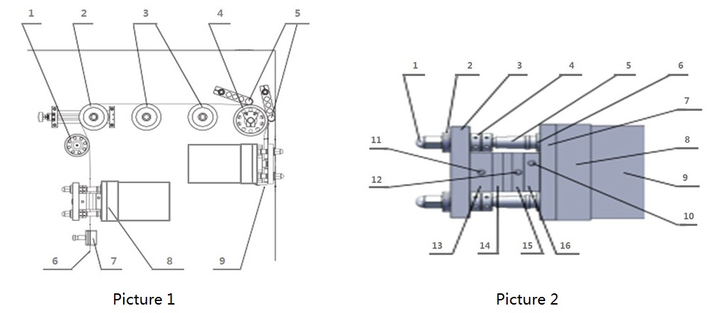
[Embossing Station Architecture] 1. Ball Nut | 2. Butterfly Spring | 3. Embossing Cover Plate | 4. Adjusting Nut | 5. Embossing Guide Pillar | 6. Embossing Guide Sleeve | 7. Embossing Guide Plate | 8. Protective Cover | 9. Embossing Box | 10. Clamp Handle | 11. Handle 1 | 12. Handle 2 | 13. Embossing Upper Plate | 14. Embossing Upper Mold | 15. Embossing Lower Mold | 16. Embossing Lower Plate