
Schematic Diagram: DPH Series Blister Machine Punching Station Architecture and Calibration
05/19/2019
Engineering Note: This technical documentation was originally published in 2019. It has been comprehensively updated on November 1, 2026, to reflect the latest advancements in the DPH series kinematic parameters and mechanical calibration standards.
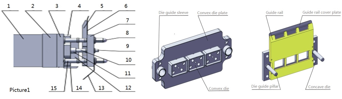
In the punching station of the DPH series Blister Machine, individual blister cards are precisely cut from the formed and sealed web. This action occurs exclusively during the stationary dwell time of the multiple-stroke intermittent indexing cycle. The web is rigidly clamped in position, allowing the convex die to press down into the concave die, shearing the blister cards from the waste skeleton with absolute dimensional accuracy.
1. Standard Operating Procedure (SOP): Punching Die Changeover
- Safety Protocol: Strictly power off the blister machine before initiating any physical tooling replacement to prevent accidental actuation.
- Tooling Extraction: Unscrew the four ball head nuts [8]. Withdraw the concave die [7], the guide rail [5], and the die guide pillars [10]. Next, remove the securing screws on the convex die plate [4] to extract the entire convex assembly.
- New Tooling Installation: Mount the new convex die plate [4] onto the punching guide plate [3], leaving the screws finger-tight for initial alignment. Install the new concave die [7] over the four punching station pillars [15], ensuring the guide pillars [10] smoothly insert into the corresponding guide sleeves [11]. Once aligned, apply final torque to the convex die plate screws and firmly secure the ball head nuts [8].
2. Kinematic Principle of the Punching Roller Index
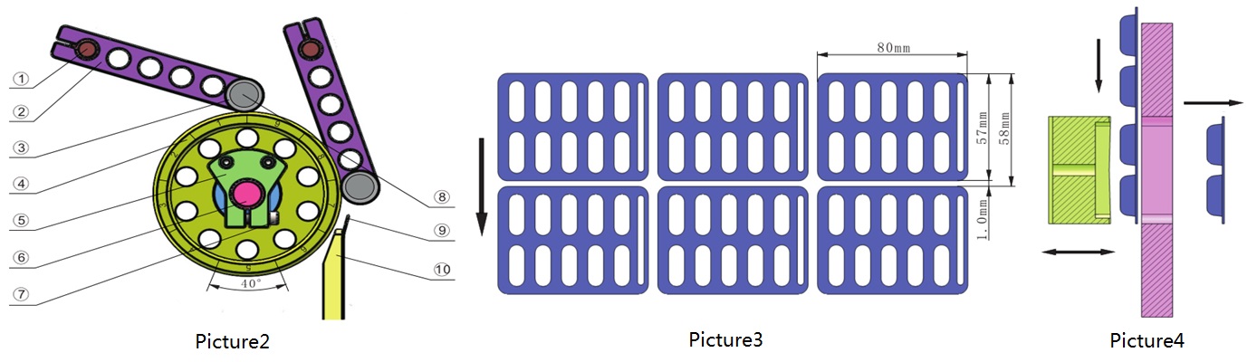
To feed the web, push the handle [8] to lift the swing arm [2]. Thread the formed and sealed web into the punching roller index, ensuring the formed blister cavities nest perfectly into the corresponding recesses of the roller. Lower the swing arms to engage the press roller [3] against the web. During operation, the servo-driven roller index precisely advances the web along the guide rail [10] into the punching dies.
3. Servo Index Angle Calibration (HMI Parameter Setup)
The rotational step angle of the servo roller index must be precisely calculated based on the product format. For example, consider an 80 × 57mm blister card, where 57mm represents the indexing machine direction (pitch length per stroke).
- Mathematical Calculation: Determine the total number of blister cards mapped around the circumference of the format-specific roller. If the roller accommodates 9 cards along its circumference, one complete revolution (360°) corresponds to 9 indexing strokes. Therefore, the step angle per stroke is: 360° ÷ 9 = 40°.
- HMI Integration: This calculated angle (40°) must be inputted into the machine’s HMI. Incorrect data entry will result in critical punching misalignment.
- Mechanical Micro-Adjustment: After HMI setup, execute a test cycle. If the punched card margin is asymmetrical, loosen the locking screw [7]. Manually rotate the roller by a micro-angle to physically offset the web registration into the cutting die. Once perfect concentricity is achieved, re-tighten the locking screw [7].