
Schematic Diagram: DPH Series Blister Machine Forming Station Workflow and Tooling Calibration SOP
01/03/2019
The DPH series Blister Packaging Machine utilizes a pneumatic thermoforming architecture. Following the heating phase, the pliable PVC web advances into the forming station. The lower forming mold elevates to close against the upper mold, where positive compressed air (4 to 6 bar) shapes the blister cavities. For complex or deep-draw cavity geometries, a mechanical “plug-assist” mechanism physically pre-stretches the heated film prior to air injection, ensuring uniform wall thickness distribution. Upon mold opening, the formed web is rapidly cooled to rigidify the structure before advancing via the traction mechanism.
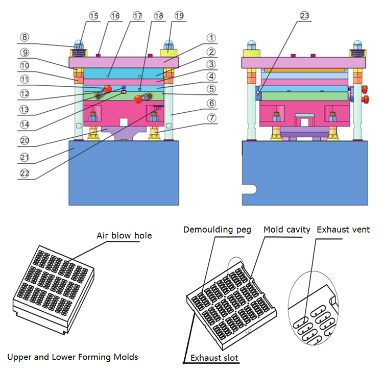
1. Tooling Changeover Protocol
- Upper Mold Replacement: With the machine powered off and the lower mold at its lowest stroke, loosen the fastening bolt [16]. Extract the upper forming mold [3] from the soleplate [2], insert the new format tooling, and re-secure the bolt.
- Lower Mold Replacement: Loosen the lock handle [11] and pivot the swing arm [12] to disengage. Extract the lower mold [4] via the handle [13] along the guide rail [14]. Insert the new mold until it registers against the stop block [23], pivot the swing arm into the lock pit [18], and lock the format in place.
2. Lateral Alignment Calibration
To correct downstream registration issues between the formed blister cavities and the rotary sealing station, loosen the lock bolt [22]. This allows micro-adjustments of the lower forming mold’s lateral position along the web axis. Retighten the bolt once absolute alignment is achieved.
3. Forming Pressure Calibration
Inadequate mold clamping pressure can cause pneumatic leakage, resulting in defective cavity formation. To calibrate:
- Inch the machine until the lower forming mold reaches Top Dead Center (TDC), where the compressed air injection initiates.
- Loosen the lock nut [10] and thread the lower nut [9] downward. Rotate all four upper nuts [8] equally to evenly increase the clamping pressure between the molds until air leakage is eliminated. Re-engage the lower nut [9] and lock nut [10].
- Critical Engineering Constraint: Always utilize the minimum clamping pressure required for proper formation. Excessive pressure induces premature wear or catastrophic failure of the forming cam. WARNING: Pressure adjustments must ONLY be executed when the lower mold is at absolute TDC; adjusting out-of-phase will cause severe mechanical damage.