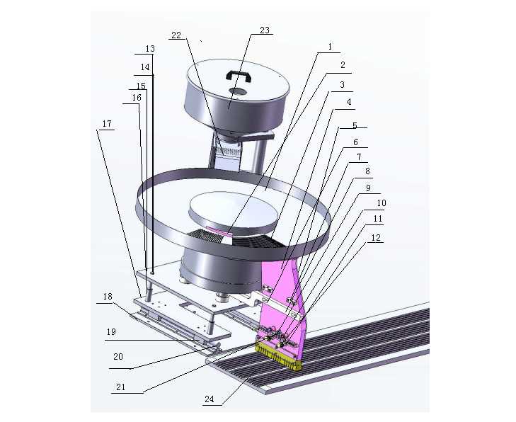
Schematic Diagram: DPH Series Blister Machine Vibratory Feeder Architecture and Calibration SOP
02/20/2019
The vibratory feeder is engineered to handle a diverse range of solid dosage forms, including flat, oblong, and oval tablets, as well as capsules with minimal bevels. While primarily utilized in continuous-motion Blister Packaging Machines, this versatile module is fully compatible with intermittent architectures. The feeding sequence initiates as the product exits the bulk hopper [23] via the linear vibratory conveyor [22]. The product transfers to the disk vibratory conveyor [1], where centrifugal circular motion aligns and directs the dosage down the slant plate [3] into the grooved feeding plate [4]. The product then drops vertically into the formed blister cavities.
Standard Operating Procedure (SOP): Vibratory Track Calibration
- 1. Guide Rail Alignment & Gap Calibration: Install the guide rail [24] and mount the feeder module onto the designated feeding zone. Precisely align the grooves of the feeding plate [4] with those of the guide rail [24]. Utilize the adjusting screw [7] to calibrate the physical gap between the feeding plate and the guide rail according to the specific tablet dimensions. Once calibrated, lock the feeding plate onto the support plate [8].
- 2. Vertical Clearance Adjustment: The clearance gap between the disk vibratory conveyor [1] and the feeding plate [4] must be tailored to the product thickness. Adjust the elevation of the upper adjusting plate [15] by manipulating the upper and lower adjusting nuts [13, 14] until the optimal vertical tolerance is achieved.
- 3. Slant Plate Synchronization: The transfer grooves within the slant plate [3] must achieve absolute alignment with the grooves in the feeding plate [4]. Modulate the position of the lower adjusting plate [17] via guide rod 1 [10] and guide rod 2 [19] to shift the disk vibratory conveyor [1]. Secure the mechanism using the locking block [21] once aligned.
- 4. Lateral Axis Centering: Finalize the setup by calibrating the lateral (left-to-right) alignment between the feeding plate [4] and the slant plate [3]. Shift the positioning bracket [25] to center the components, then firmly lock the bracket to prevent operational drift.